
In the field of electrical engineering, where the reliability of energy networks is paramount, maintaining the insulation of equipment is a critical challenge. An insulation failure can lead to costly outages, safety risks, or even widespread blackouts. Among the most effective and widely used diagnostic tools is the Tan Delta test, also known as the Dissipation Factor Test or Loss Angle Test.
This test, most commonly referred to as “Tan Delta,” precisely evaluates the dielectric quality of insulating materials by quantifying energy losses due to their imperfections. But beyond its name, what is the underlying principle of this test? Is it exclusively dedicated to power transformers, or does it extend to other equipment?
In this detailed article, we delve into the heart of this method, drawing on in-depth technical explanations, illustrative diagrams, and visuals from phase diagrams, test connection schematics, and practical guides. We will explore its fundamental principle, implementation methods, diverse applications, limitations, and future perspectives, providing a comprehensive and accessible overview for engineers, technicians, and maintenance managers.
Article Content
What is the Tan Delta Test? Theoretical Foundations and Practical Context
The Tan Delta test is a non-destructive measurement technique that analyzes the dielectric properties of an insulating material by measuring the energy losses caused by its imperfections. In ideal theory, a pure insulator behaves like a perfect capacitor: under the application of an alternating voltage (AC), the current passing through it is purely capacitive and leads the voltage by exactly 90 degrees (π/2 radians). There is no resistive component in phase with the voltage, meaning a total absence of ohmic or dielectric losses.
However, in the real world, no insulator achieves this absolute purity. Environmental or intrinsic factors—such as infiltrated moisture, impurities in the insulating oil, microcracks due to aging, or partial discharges—introduce a resistive component. This distorts the phase diagram, creating a loss angle δ (delta) between the voltage vector (U) and the total current vector (I). The tangent of this angle, denoted tan delta, precisely quantifies this imperfection and corresponds to the loss factor or dissipation factor (Dissipation Factor, DF).
The lower tan delta is (close to zero), the better the insulator performs; a high value signals potential degradation. Typically expressed as a percentage (%) or in dimensionless units (×10^{-3}), a tan delta below 0.5% indicates healthy insulation for most high-voltage equipment. This test is particularly sensitive to variations, making it an early indicator of issues well before a catastrophic failure.
To illustrate this concept, consider the phase diagram shown in Figure below (based on a provided comparative illustration). On the left, the ideal cable system (R = ∞) shows a purely capacitive current (Ic) perpendicular to the voltage U, with an angle δ = 0°. On the right, the real system with losses (R ≠ ∞) introduces a resistive current (Ir) in phase with U, and a slightly offset capacitive current (Ic). The angle δ emerges between Ic and the resulting vector I, visually highlighting how losses “tilt” the diagram toward energy dissipation. Mathematically:
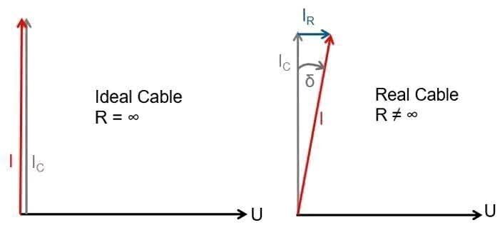
- Capacitive current (Id or Ic): quadrature with U (90° lead).
- Loss current (Ir): in phase with U (0°).
- tan δ = Ir / Id, where the ratio reflects the proportion of losses relative to the ideal component.
This vector representation is fundamental to understanding why the Tan Delta test is a “thermometer” for insulators: it captures subtle deviations that escape classical ohmic measurements.
The Fundamental Principle of the Tan Delta Test: From Theory to Practical Measurement
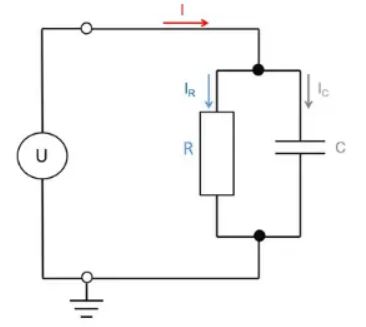
At the core of the Tan Delta test lies a simple yet powerful modeling: the insulating sample is treated as an equivalent series capacitor (C in parallel with R). An AC voltage source is applied, and an analyzer simultaneously measures the magnitude and phase of the resulting current relative to the voltage. The tangent of the phase angle δ directly provides tan δ.
The experimental process is iterative and progressive:
- Preparation: The equipment is disconnected from all power sources, grounded for safety, and test points (high-voltage terminals, low-voltage terminals, and ground) are identified.
- Voltage Application: A test voltage (typically 0.5 kV to 10 kV, depending on the equipment) is applied in AC mode, at a controlled frequency.
- Measurement: The device records the total current, decomposes it into Ir and Id components, and calculates tan δ. Multiple readings at different voltage or frequency levels allow for diagnostic curve plotting.
- Interpretation: Values are compared to normative thresholds (e.g., IEC 60076-3 for transformers) and historical data to detect trends.
This test is highly sensitive to degradations:
- Moisture or openings in windings: Increases Ir, thus tan δ (up to +20% or more).
- Impurities in insulating oil or partial discharges: Introduces non-linear peaks at high voltages.
- Aging: Older equipment shows tan δ 2 to 5 times higher than new ones, due to depolymerization of insulating paper or oxidation.
Typical values for healthy insulation range from 0.3% to 0.5% (or 3 to 5 × 10^{-3}), but stricter thresholds apply to generators (< 0.3%) or cables (< 0.1%). Beyond these, corrective maintenance is imperative.
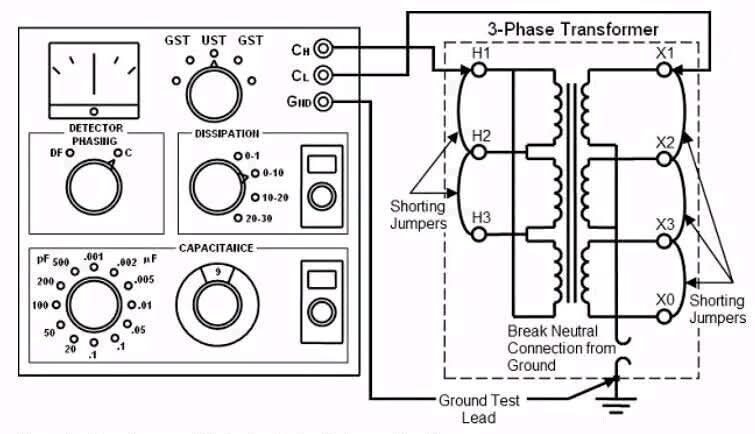
Figure below illustrate typical connection diagram for capacitance and dissipation factor testing on a three-phase transformer. This schematic show a multifunctional analyzer connected to the high-voltage windings (H1, H2, H3), low-voltage windings (X1, X2, X3), and the floating neutral (Break Neutral). Shorting jumpers connect the secondary windings to simulate a load, while phase detectors (DF, OC) and meters (GST for guard voltage, UST for test voltage) measure parameters. The ground (Ground Test Lead) ensures a safe reference. These setups, often used with portable devices like the Doble M4100, minimize interference and maximize accuracy.
Finally, a simplified practical guide (Figure below) summarizes the working principle: disconnect the equipment, attach the test set to the bushings and ground terminals, apply voltage progressively, record values at various levels, and compare with standard limits. It includes a clear interpretation table:
- tan δ > 1%: Dangerous – Requires immediate correction.
- 0.5% to 1%: Questionable – Requires careful monitoring.
- < 0.5%: Good – No action required.
This guide, inspired by standards like IEC 60270, emphasizes a step-by-step approach to avoid human errors.
Implementation Methods: Variants and Optimizations
The flexibility of the Tan Delta test lies in its execution modes, tailored to the equipment and field constraints. Two dominant approaches prevail:
- Variable Voltage at Fixed Frequency: Increasing voltage (e.g., 1 kV, 5 kV, 10 kV) at a fixed 50/60 Hz. Ideal for detecting partial discharges, which manifest as a “tip-up” (abrupt rise in tan δ beyond a threshold). Objective: Identify structural weaknesses under stress, as in transformer bushings.
- Variable Frequency at Fixed Voltage: Constant voltage (e.g., 5 kV) with frequency sweep (0.01 Hz to 1 kHz). Useful for aging diagnostics, as interfacial losses (polarization) decrease at low frequencies. Effective for large transformers where load currents mask anomalies at 50 Hz.
Hybrid methods, such as the Maxwell bridge test or with automated analyzers (e.g., Omicron CPC 100), integrate capacitance (C) and tan δ for a comprehensive evaluation. Figure 4 shows a simplified schematic: a test generator applies U, measuring Ir and Ic via an equivalent RC bridge, with tan δ = Ir / Ic displayed in real time.
These variants, combined with plotting software (tan δ vs. U or f curves), enable nuanced analysis, essential for harsh environments (humidity, dust).
Applications: Versatility Beyond Power Transformers
Far from being confined to power transformers—where it monitors oil, windings, and bushings—the Tan Delta test extends to any critical insulating equipment:
- Cables: Detection of degradations in HVDC or XLPE lines, via in-situ tests to avoid costly excavations.
- Bushings: Evaluation of HV connections, where tan δ > 0.5% signals contamination.
- General Insulators: In SF6 circuit breakers or epoxies.
- Transformers: Predictive monitoring of windings and oil.
- Generators: Stator diagnostics, with thresholds < 0.3% for Class F.
- Capacitors: Purity verification, tan δ < 0.1%.
- Surge Arresters: Control of ZnO varistors against overvoltages.
In condition-based maintenance (CBM) programs, it reduces unplanned downtime by 30-50%, from thermal power plants to smart grids.
Limitations, Interpretations, and Future Perspectives
Despite its strengths, the Tan Delta test is not without limitations:
- Sensitivity to Interference: Electromagnetic fields or extreme temperatures bias measurements; in-situ calibration is crucial.
- Contextual Interpretation: Absolute values vary with humidity (increase of 10-20% per 10% relative humidity); cross-referencing with IR (insulation resistance) or PD (partial discharges) is recommended.
- Non-Destructive but Invasive: Requires disconnection, limiting online use (though real-time versions are emerging).
Standards like IEC 60076 and IEEE C57.152 guide interpretation, with historical data for trend detection (e.g., >20% rise in one year = alert).
Perspectives: IoT analyzers with wide bandwidth (up to 10 kHz) and AI for predictive analysis are revolutionizing the field, integrating big data for Industry 4.0 maintenance. Innovations like optical sensors reduce disconnection needs.
Conclusion: An Indispensable Pillar for Electrical Resilience
The Tan Delta test, through its elegant principle—modeling the insulator as an imperfect capacitor via tan δ = Ir / Id—offers unparalleled preventive diagnostics. From phase diagrams to mobile guides, its visual illustrations (as presented) facilitate understanding and application. Beyond transformers, it safeguards all electrical assets, anticipating failures and optimizing costs. For professionals, adopting it is not optional but essential in a world where reliable energy is vital. Integrate it into your routine: measure, analyze, and secure the future of your networks! If you’re an engineer, test it on-site and compare with these schematics for enhanced mastery.