
During transformer commissioning, one of the most important diagnostic procedures is the power factor test. This test assesses the dielectric losses in the transformer’s insulation system, which are directly related to insulation quality and integrity.
For dry-type transformers, the power factor test helps identify potential insulation deterioration due to moisture, contamination, carbonization, or other degradation mechanisms that may affect long-term performance and safety.
Article Content
What is the Power Factor Test?
The power factor test measures the phase angle between an applied AC voltage and the resulting current flowing through the insulation. The power factor itself is defined as:
Power Factor (cos θ) = (Watts) / (Volts × Amperes)
It is expressed as a percentage and represents the ratio of power dissipated (dielectric losses) to the apparent power supplied during the test.
A low power factor value indicates good insulation, while a high power factor value suggests possible insulation deterioration or contamination.
Purpose of the Power Factor Test
The main objectives of performing a power factor test on a dry-type transformer during commissioning are:
- Establish a Baseline: Provides reference values for future maintenance comparisons.
- Detect Insulation Deterioration: Identifies defects such as moisture ingress, dirt, or partial discharges.
- Verify Manufacturing Integrity: Confirms that insulation materials and construction meet specifications before energization.
- Ensure Safety: Prevents insulation failure that could lead to transformer faults or outages.
Transformers Typically Tested
Power factor testing applies to various transformer types, including:
- Two-winding transformers
- Three-winding transformers
- Autotransformers
- Instrument transformers
This test may also be referred to as the dielectric loss angle, dissipation factor test, tan delta, or doble test.
General Testing Conditions
Before performing the power factor test, several safety and preparation steps must be followed:
- De-energize and isolate the transformer completely from the power system, including the neutral connection.
- Ensure the transformer enclosure is grounded properly, particularly when testing spare units.
- Short-circuit all terminals of each winding (including neutral) to minimize the effect of winding inductance.
- If equipped with a load tap changer (LTC), set it to the neutral position.
Always verify that all connections are correct and safe before energizing the test circuit.
Recommended Test Voltage Levels
The test voltage applied during power factor testing is typically below the normal operating stress levels of the insulation. The table below summarizes standard recommendations for dry-type transformers:
| Winding Rating (kV) | Line-to-Line Test Voltage (kV) | Line-to-Ground Test Voltage (kV) |
|---|---|---|
| Above 14.4 | 2 and 10 | 2 and 10 |
| 12 – 14.4 | 2, 10, and at operating voltage | At operating voltage |
| 5.04 – 8.72 | 2 and 5 | 2 and 5 |
| 2.4 – 4.8 | 2 | 2 |
| Below 2.4 | 1 | 1 |
Note: When transformer windings have a neutral insulation rating lower than the line insulation rating, the test voltage should not exceed the neutral insulation rating.
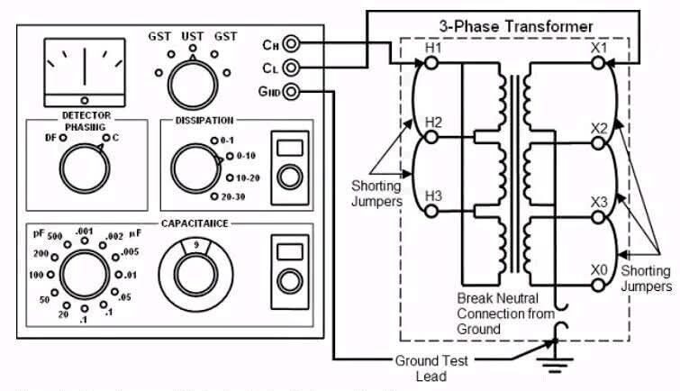
Power Factor Test Connections
For two-winding dry-type transformers, the test connections vary depending on whether the high-voltage (HV) or low-voltage (LV) winding is being tested.
- The HV winding test measures insulation between the HV winding and ground.
- The LV winding test measures insulation between LV winding and ground.
- Interwinding tests assess insulation between HV and LV windings.
Power Factor Test Procedure (Two-Winding Dry-Type Transformer)
Step 1: Isolation and Grounding
- Isolate the transformer from all incoming and outgoing cables.
- Apply working grounds to all disconnected cables.
- Maintain sufficient clearance between disconnected cables and transformer terminals.
Step 2: Connection Setup
- Connect the test leads according to the manufacturer’s power factor test diagram.
- Always ground the previously energized terminal using a grounding stick before making or changing connections.
Caution: Never remove the grounding connection until all circuit changes are completed.
Step 3: Apply Test Voltage
- Apply the appropriate test voltage based on the transformer’s rated winding voltage (refer to Table).
- Record the measured current, voltage, and watts.
Step 4: Calculate Power Factor
Compute power factor using the formula:
- \text{Power Factor} = \frac{\text{Watts}}{E \times I}
where:
- E = Applied voltage
- I = Current measured
- Watts = Power dissipated in the insulation
Measuring Capacitance and Dissipation Factor
Along with the power factor, it is common to measure capacitance and the dissipation factor (tan δ) to assess insulation health.
A rise in dissipation factor indicates aging, moisture ingress, or contamination of insulation materials. As insulation degrades, more energy converts into heat, accelerating further deterioration.
Regular testing helps establish trend analysis for predictive maintenance and early detection of faults.
Tan Delta and Power Factor Interpretation
- Low tan delta (0.5% – 1%) → Good insulation condition.
- Moderate tan delta (1% – 2%) → Possible contamination or partial aging.
- High tan delta (>2%) → Significant insulation deterioration; corrective action recommended.
Safety Precautions
- Always de-energize and isolate the transformer before testing.
- Use insulated tools and grounding sticks.
- Ensure all terminals are properly shorted where required.
- Never exceed the rated test voltage.
- Follow the test equipment manufacturer’s safety guidelines.
Conclusion
Performing the power factor test on a dry-type transformer during commissioning is a critical step in ensuring the reliability and safety of the power system.
It provides valuable insights into the condition of the insulation system, detects early signs of deterioration, and helps establish baseline values for future maintenance.
By adhering to standardized testing procedures, using proper test voltages, and ensuring safe practices, engineers can verify transformer health and prevent costly failures in the field.