
Distance protection schemes play a vital role in ensuring reliable and speedy fault clearance on transmission lines. The fundamental idea behind distance protection is to measure the impedance between the relay location and the fault point, enabling the relay to detect faults within set zones. Conventional time-stepped distance protection, for instance, sets an instantaneous Zone 1 reach to about 80% of the line length and uses time-delayed backup zones (Zone 2, Zone 3) to protect the remaining line section and adjacent lines.
However, certain power system conditions—such as the requirement for high-speed fault clearance or high-speed auto-reclosing—make conventional stepped distance protection insufficient. To address these needs, communication-assisted schemes have been introduced. These schemes interconnect distance relays at both ends of the protected line via a communications channel, ensuring faster clearance of end-zone faults by coordinating relay actions across line terminals.
Below is an overview of several key distance protection schemes, starting with the Zone 1 extension approach and moving through the various communication-assisted schemes for enhancing speed and security of fault clearance.
Article Content
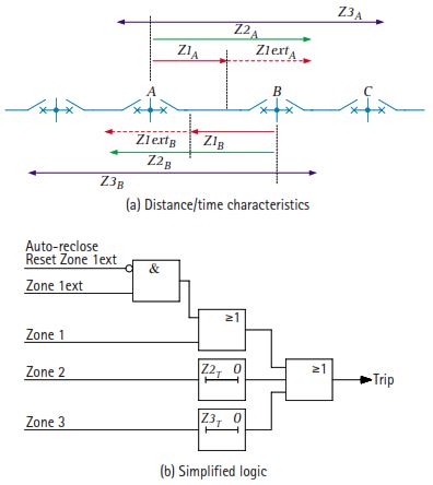
Zone 1 Extension Scheme
Also referred to as the Z1X scheme, this approach aims to provide instantaneous tripping for the entire line length in situations where a communications channel is not available or has failed. It also finds application when used in conjunction with high-speed auto-reclose.
Basic Concept
- Each relay’s Zone 1 has two possible reach settings. One is set to cover roughly 80% of the line length, while the other (Z1X) is typically extended to around 120% to overreach the line.
- Under healthy communication conditions (or if auto-reclose is out of service), the relay automatically reverts to the normal 80% Zone 1 reach.
Operation
- If a fault occurs anywhere within the extended Zone 1 reach, the relay trips instantaneously.
- An auto-reclose cycle is initiated, and the Zone 1 reach is reset to 80% prior to the breaker re-closing attempt.
- If the fault is transient, the breaker re-closes successfully; if it is permanent, the backup zones coordinate to clear.
Drawbacks
- The primary disadvantage is the possibility of over-tripping for external faults. Because Zone 1 is extended, external faults within the extended reach can cause unnecessary tripping of additional circuit breakers, especially in multi-terminal or double-circuit configurations. This can increase system disturbances and breaker maintenance.
Transfer Trip Schemes
In transfer trip (also called intertrip) schemes, one end of the line sends a “trip” signal to the remote terminal upon detecting a fault, allowing instantaneous clearance on both ends of the faulted section. Several variations exist:
1. Direct Under-Reach Transfer Tripping Scheme
- The local Zone 1 element both trips the local breaker and directly sends a trip command to the remote end.
- While fast, this arrangement is vulnerable to maloperation due to channel interference or accidental keying. Hence, it is seldom used in modern systems.
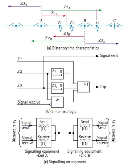
2. Permissive Under-Reach Transfer Tripping (PUP) Scheme
- Improves security over the direct version by requiring both the local (Zone 1) and remote (Zone 2) relays to detect the fault before permitting instantaneous tripping at the remote end.
- A time-delayed reset of the “signal received” element ensures reliable remote tripping, especially when there is a small infeed from the remote terminal.
3. Permissive Under-Reaching Acceleration Scheme
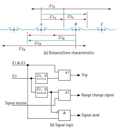
- Primarily used in older relays with switched measuring elements. The relay’s reach is switched from Zone 1 to Zone 2 immediately upon receiving a permissive signal, accelerating the tripping if the fault is in the 80–120% region.
- Has limited modern use due to changes in distance relay design.
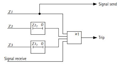
4. Permissive Over-Reach Transfer Tripping (POP) Scheme
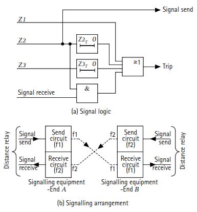
- Uses a Zone 2 (or forward over-reaching) element to key the communication channel. The remote end must also detect the fault in forward direction to allow tripping. Hence, it is sometimes referred to as a “directional comparison” arrangement.
- Commonly used on short lines, especially if the forward over-reaching Zone 2 element offers better coverage of high-resistance faults than Zone 1.
5. Weak Infeed Conditions
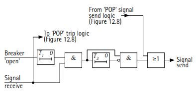
- Under conditions where one end has little or no infeed (e.g., open breaker or remote bus disconnected), features such as “Weak Infeed Echo” or “Weak Infeed Trip” can still allow fast tripping at the strong source end and trip the weak end if the voltage is depressed due to the fault.
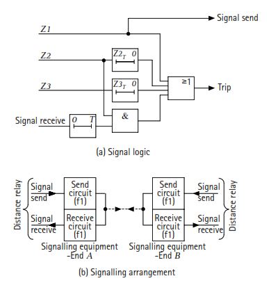
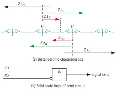
Blocking Scheme
A blocking scheme inverts the logic used in transfer trip schemes. Instead of sending a “trip” or “permissive” signal for internal faults, the relay sends a blocking signal when it detects an external fault in the reverse direction. Thus, if a forward distance element sees a fault but no block signal is received, it trips instantly.
Basic Principle
- Over-reaching distance elements (e.g., Zone 2) look into the protected line. If they pick up, they will trip unless a block signal arrives from the remote end.
- Reverse-looking elements at the remote end detect external faults behind the line and key the channel to transmit a “block” signal, preventing unwanted tripping.
Operating Times
- Typically, a short intentional time delay (e.g., a “start to latch” delay) is introduced to ensure the reverse-looking relay and communication channel can block the forward element for external faults.
- If the signal fails, the scheme defaults to conventional distance protection, with no instantaneous tripping in the end zone.
Current Reversal Guard
- In parallel line configurations, the reversal of current from one circuit to another (after a breaker has tripped) can cause transient blocking-signal issues. A reset timer on the blocking signal ensures that a brief loss of signal does not mistakenly enable an unwanted trip.
Directional Comparison Unblocking Scheme
Often referred to as a “deblocking overreach” method, this scheme employs a continuous “block” (or guard) signal. When an over-reaching distance element operates, it shifts the signal from the block frequency to an “unblock” frequency, permitting the remote terminal to trip if its own over-reaching element also detects the fault.
Dependability vs. Security:
- Loss of channel or certain short-circuits can momentarily interrupt the block frequency. The scheme then enters a brief interval (e.g., 100–150 ms) in which it allows tripping even if it does not detect the unblock frequency. This ensures better dependability.
- After this interval, only the unblock frequency will permit remote tripping, improving security against false trips for external faults.
“Weak Infeed Echo” and “Weak Infeed Trip” can be applied similarly to ensure full line coverage under open breaker or no-load conditions.
Comparison of Transfer Trip and Blocking Relaying Schemes
In practice, modern numerical distance relays often include multiple logic options (permissive under-reach, permissive over-reach, blocking, unblocking, and specialized weak-infeed features), and the choice may depend on a utility’s operating policies and the nature of the communications channel. Key comparative points:
- Speed:
- Transfer trip (especially permissive under-reach or over-reach) can be slightly faster since it does not rely on receiving a block signal. Blocking schemes usually introduce a short delay to allow time for the block signal to be sent for external faults.
- Security vs. Dependability:
- Blocking schemes are considered more secure against false trips when the channel is lost or noisy, because the default action without a blocking signal is to trip. Meanwhile, transfer trip schemes can become less dependable if the channel fails, since the permissive or direct trip signal never arrives.
- Adaptability to Infeed Conditions:
- Both approaches can deal with weak infeed (or open breaker) situations, but require additional features such as “Weak Infeed Echo” or direct intertripping.
- Channel Requirements:
- Permissive schemes typically require two communication channels (duplex) for over-reach schemes. Blocking schemes only need a single frequency, though directional comparison unblocking uses continuous transmission on one frequency and shifts to another.
Overall, selecting a scheme involves balancing operational speed, security requirements, complexity, and communication channel reliability. Many modern relays offer all of these schemes so that protection engineers can choose or dynamically switch between them based on system conditions.
Conclusion
Distance protection schemes form the backbone of transmission line protection, ensuring fast, selective, and secure fault clearance. While conventional stepped distance protection provides basic functionality, communication-assisted schemes—such as transfer trip, blocking, and unblocking methods—enhance both speed and reliability.
Modern numerical relays often integrate all these schemes, allowing utilities to dynamically select the optimal logic based on system configuration, communication quality, and operational requirements. Choosing the right scheme ensures a balanced trade-off between security, dependability, and speed, thereby enhancing overall grid stability.