
Medium Voltage (MV) switchboards are critical components in electrical distribution networks, responsible for controlling, protecting, and isolating electrical equipment. The power supply modes for these switchboards vary based on the required level of redundancy, reliability, and operational flexibility. These modes determine how supply sources connect to the busbars and feeders, ensuring continuity of power while minimizing downtime during faults or maintenance.
The choice of supply mode depends on factors such as the site’s power demands, security requirements, and cost considerations. Below, we explore the primary MV switchboard power supply configurations, drawing from established electrical engineering practices. Each mode includes a description of its structure, operation, and advantages.
Article Content
1. Single Busbar with One Supply Source
In this basic configuration, a single busbar is fed by one power source. The source connects directly to the busbar, which then distributes power to multiple MV feeders.
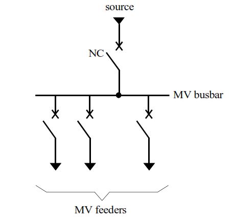
- Operation: If the supply source fails or requires maintenance, the entire busbar and all connected feeders lose power until the issue is resolved.
- Advantages: Simple and cost-effective, suitable for applications with low redundancy needs.
- Disadvantages: Low fault tolerance; any source disruption affects the entire system.
This mode is often used in small-scale or non-critical installations where downtime is acceptable.
2. Single Busbar with No Coupler, Two Supply Sources
Here, two supply sources connect to a single busbar without a coupling device between them.
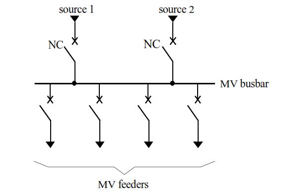
- Operation: One source actively feeds the busbar while the other acts as a backup. In case of failure in the primary source, the system switches to the secondary source. However, a busbar fault de-energizes all feeders.
- Advantages: Provides basic redundancy for source failures, improving reliability over a single-source setup.
- Disadvantages: No isolation for busbar issues, leading to total outage if the busbar fails.
This setup is common in medium-priority sites where source redundancy is prioritized over busbar protection.
3. Two Bus Sections with Coupler, Two Supply Sources
The busbar is divided into two sections, each fed by a separate source, with a coupler circuit-breaker connecting the sections.
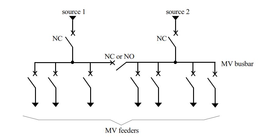
- Operation: Each source powers its respective bus section. The coupler can remain open or closed. If one source fails, the coupler closes, allowing the remaining source to feed both sections. A fault in one section affects only half the feeders.
- Advantages: Better fault isolation and partial continuity during failures or maintenance.
- Disadvantages: Slightly more complex wiring and control systems.
Ideal for facilities requiring moderate redundancy, such as industrial plants.
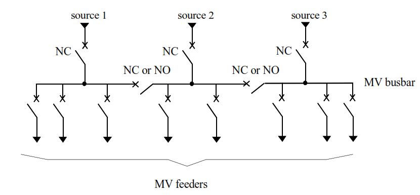
4. Single Busbar with No Coupler, Three Supply Sources
A single busbar is connected to three supply sources, typically with two operating in parallel and one as backup.
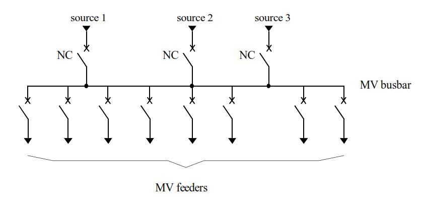
- Operation: Two sources provide normal power, with the third ready for failover. Loss of one or two sources allows the remaining one(s) to maintain supply. Busbar faults, however, outage the entire system.
- Advantages: High source redundancy for critical loads.
- Disadvantages: Vulnerable to busbar failures.
This mode suits high-availability environments but still relies on a single busbar.
5. Three Bus Sections with Couplers, Three Supply Sources
The busbar is split into three sections, each with its own source, connected via couplers.
- Operation: Each source feeds its section, with couplers allowing load sharing or failover. Loss of a source prompts the adjacent coupler to close, redistributing power (e.g., one source feeds two sections). Section faults isolate only the affected part.
- Advantages: Excellent segmentation for fault containment and maintenance without full outages.
- Disadvantages: Increased complexity and cost due to multiple couplers.
Used in large-scale operations like data centers or hospitals.
6. Two Busbars with Two Connections per Outgoing Feeder, Two Supply Sources
Dual busbars (BB1 and BB2) are present, with each feeder connectable to either via isolators. A coupler connects the busbars.
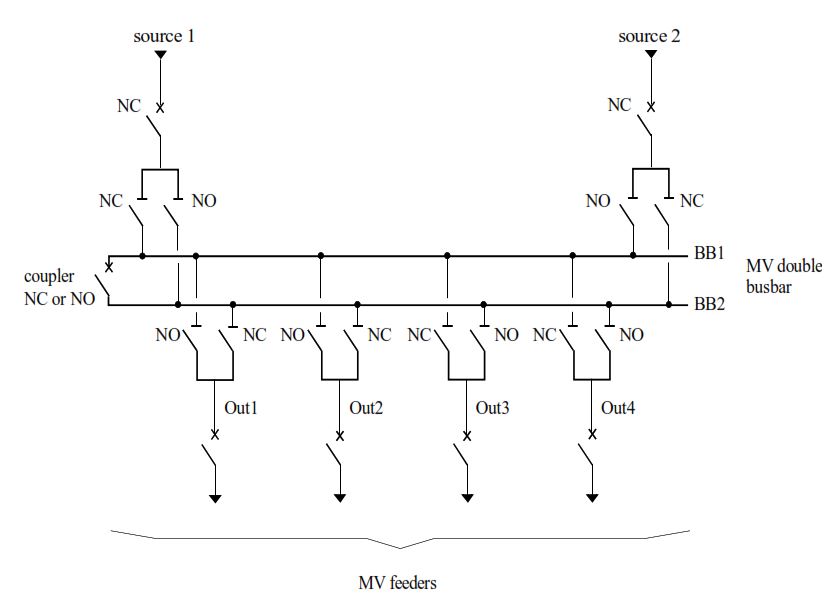
- Operation: Feeders select a busbar via isolators (only one closed per feeder). Sources divide loads between busbars. Source failure prompts the remaining source to take over via the coupler. Busbar faults allow switching to the healthy busbar.
- Advantages: High flexibility and redundancy; maintenance on one busbar doesn’t interrupt service.
- Disadvantages: Requires more isolators and careful management.
This configuration enhances operational resilience in dynamic environments.
7. Two Interconnected Double Busbars
Similar to the previous but with busbars split into two switchboards, each with double busbar setups, interconnected via couplers.
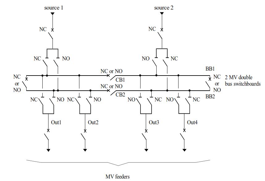
- Operation: Each switchboard handles a subset of feeders. Couplers enable load balancing and failover across switchboards. Faults are isolated to minimize impact.
- Advantages: Greater flexibility and reduced feeder count per busbar for better management.
- Disadvantages: Higher installation costs.
Suitable for expansive networks needing scalable redundancy.
8. Duplex Distribution System
Features a double busbar with drawout circuit-breakers for sources and feeders, allowing easy repositioning.
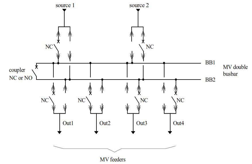
- Operation: Sources and feeders use paired cubicles with one shared circuit-breaker per pair. Repositioning the breaker switches busbar allegiance. Couplers aid in failover.
- Advantages: Economical (fewer breakers) and flexible for maintenance.
- Disadvantages: Manual intervention for repositioning may introduce delays.
This system balances cost and reliability for medium-critical applications.
In summary, MV switchboard power supply modes range from simple single-source setups to advanced multi-busbar configurations with couplers. Selecting the appropriate mode involves balancing reliability, cost, and complexity. For critical infrastructure, modes with multiple sources and sectionalization are preferred to ensure uninterrupted power. Always consult standards like IEC 62271 for implementation.