
Magnetising inrush is a transient electrical phenomenon that primarily occurs when a power transformer is energized. It is not indicative of a fault but rather a normal response of the transformer’s magnetic core to sudden application of voltage. However, it poses significant challenges for transformer protection systems, which must distinguish this temporary surge from actual faults to avoid unnecessary tripping. Protection relays are designed to remain stable during inrush conditions while responding swiftly to genuine issues like short circuits or overloads.
This article explores the causes, characteristics, influencing factors, and harmonic implications of magnetising inrush, drawing from established principles in transformer design and protection.
Article Content
The Phenomenon Explained
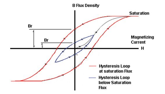
Transformers operate efficiently when their cores are magnetized near the “knee point” of the magnetizing characteristic curve—a point where the core begins to saturate. This design choice minimizes material costs, weight, and size. Under steady-state conditions, the magnetizing current required to maintain the core’s flux is relatively small, typically a fraction of the transformer’s rated current.
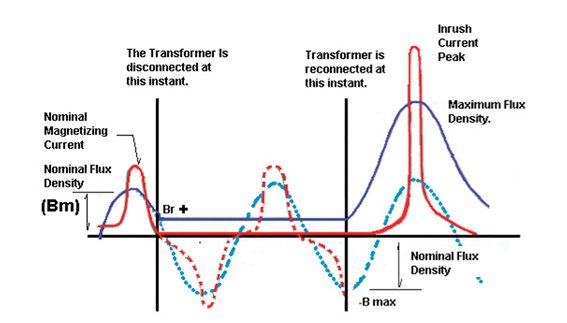
However, issues arise during energization. If a transformer winding is switched on at a point where the voltage waveform is at zero and there is no residual (remanent) flux in the core, the magnetic flux can peak at twice the normal operating level during the first half-cycle. This drives the core into deep saturation, resulting in a high, non-sinusoidal magnetizing current known as inrush current.
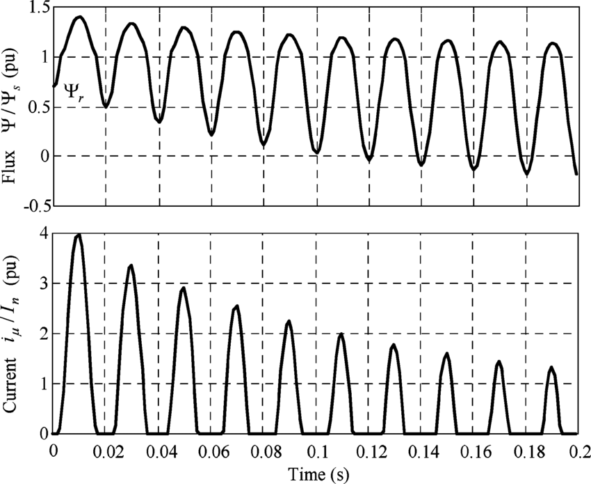
The waveform of this inrush current starts from zero and builds gradually at first, as the flux is just above any residual level and the core’s permeability is still moderate. As the flux exceeds normal levels and enters saturation, the winding’s inductance drops dramatically—approaching that of an air-core inductor. This causes the current to spike rapidly, potentially reaching 500% or more of the steady-state magnetizing current. The current then falls symmetrically to zero in the subsequent half-cycle, but the waveform is fully offset (asymmetrical) due to the DC component introduced by saturation.
This offset decays over time due to circuit losses, with a time constant ranging from 0.1 seconds for small transformers (e.g., 100 kVA) to 1 second or more for large units. Because the magnetizing characteristic is nonlinear, the decay isn’t purely exponential; residual changes in magnetizing current can persist for up to 30 minutes after energization.
In single-phase transformers, careful selection of the switching point on the voltage waveform can minimize or eliminate inrush. However, in three-phase transformers, mutual magnetic coupling between phases ensures that inrush occurs across all phases regardless of the switching instant.
Factors Affecting Magnitude and Duration
Several variables influence the severity and persistence of magnetizing inrush:
- Residual Flux: The worst-case scenario occurs when residual flux aligns with the applied voltage, pushing peak flux to 280% of normal levels and amplifying the inrush.
- Point-on-Wave Switching: Energizing at voltage zero without residual flux maximizes inrush, while switching near voltage peaks can reduce it.
- Number of Banked Transformers: Parallel or banked transformers can exacerbate inrush due to interactions between their magnetic fields.
- Transformer Design and Rating: Larger transformers with higher ratings tend to have longer decay times. Core material, winding configuration, and impedance also play roles.
- System Fault Level: Higher system impedance can dampen the inrush, while stiff (low-impedance) sources allow larger peaks.
These factors make inrush unpredictable, necessitating robust protection strategies that inhibit tripping during transients.
Harmonic Content in the Inrush Waveform
The inrush waveform is rich in harmonics due to core saturation. Under normal operation, the magnetizing current includes a third harmonic as the dominant component, with progressively smaller fifth, seventh, and higher odd harmonics.
As saturation deepens during inrush, the overall harmonic content increases. The relative proportions shift: the fifth harmonic grows and can surpass the third, while the seventh may dominate at extreme saturation levels (though this is rare in power transformers).
The asymmetrical nature of the offset inrush waveform introduces even harmonics as well, particularly a substantial second harmonic, alongside the odd ones. Typical inrush currents feature high second and third harmonics, with diminishing higher orders.
As the inrush decays, the harmonic composition evolves. This dynamic behavior is key to protection schemes: many modern differential relays use harmonic restraint (e.g., blocking on high second-harmonic content) to differentiate inrush from faults, where harmonics are less pronounced or different in makeup.
Implications for Transformer Protection
Magnetizing inrush can mimic internal faults in terms of current magnitude, potentially causing false trips in overcurrent or differential protection relays. However, its transient nature and unique harmonic signature allow for discrimination. Protection must balance sensitivity to real faults with stability during inrush to prevent outages and ensure system reliability.
In practice, relays incorporate features like second-harmonic restraint or waveform analysis to block operation during inrush. Understanding this phenomenon is crucial for engineers designing, commissioning, and maintaining power systems, as it directly impacts transformer longevity and grid stability.