
Time synchronization is one of the most important foundations of any digital substation using IEC 61850. As protection, automation, and measurement move from traditional copper wiring to Ethernet-based communication, the need for a shared and precise time reference becomes essential. Modern substations depend on synchronized measurements to operate safely. Without correct timing, protection functions may misinterpret events, fault records may become unreliable, and Sampled Values streams may drift out of alignment.
IEEE 1588, also known as the Precision Time Protocol (PTP), provides this critical timing foundation. In IEC 61850 substations, a specific timing profile called IEC/IEEE 61850-9-3 defines how IEEE 1588 must behave to meet the strict accuracy and stability requirements of protection and control. While IEEE 1588 is used in many industries, the 9-3 profile adapts it for power utility automation, where microsecond-level accuracy and stability under load are mandatory.
This article explains how IEEE 1588 works in IEC 61850 substations, why the 9-3 profile is necessary, how clocks synchronize, how switches handle timing traffic, and how Sampled Values depend on a reliable timing architecture.
Table of Contents
Why Timing Is Critical in Digital Substations
Traditional substations transmitted analog currents and voltages from the switchyard to protection relays through copper cables. Timing was implicit because all signals traveled together physically. With the shift to digital substations, merging units convert analog signals into Sampled Values and send them to protection devices over Ethernet. These Sampled Values must be aligned in time with microsecond accuracy.
If two merging units sample at different instants or drift out of alignment, protection relays may calculate incorrect values. Differential protection may see false differential currents. Distance protection may miscalculate impedance. Synchrophasors may become inaccurate. Even event logs and sequence-of-events records depend on synchronized time.
Accurate time is therefore not an optional feature. It is a core requirement of the IEC 61850 process bus. IEEE 1588 provides the timing mechanism, while the 61850-9-3 profile ensures consistent and deterministic behavior in substation networks.
How IEEE 1588 Works in Simple Terms
IEEE 1588 distributes time from a central master clock, known as the grandmaster, to all other devices in the network, known as slaves. The grandmaster sends timing messages to the slaves, which adjust their internal clocks to match the grandmaster. Because internal clocks drift naturally, these adjustments must happen continuously.
PTP uses timestamped messages to calculate the delay between master and slave and to compute any offset in their clocks. The slave updates its time based on these values. This process allows very accurate alignment, often better than one microsecond.
However, in a digital substation, ordinary network devices cannot be allowed to distort these timing messages. If a switch delays a timing packet by a variable amount, the slave clock calculates the wrong delay and sets the wrong time. For this reason, timing-aware switches are essential. These switches use either Transparent Clock or Boundary Clock mechanisms to handle PTP traffic with precision.
How PTP Messages Distribute Time
PTP uses several types of messages to distribute and maintain accurate time. The most important are Sync, Follow_Up, Delay_Req, and Delay_Resp. Together, these messages allow devices to calculate the path delay, clock offset, and required adjustments. In normal operation, a slave device receives timestamped Sync and Follow_Up messages from the grandmaster. These timestamps tell the slave what time the grandmaster had at the moment of sending the message.
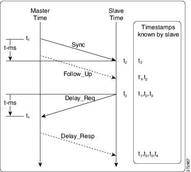
The slave then sends a Delay_Req message back to the master, which responds with a Delay_Resp message containing timestamps that indicate when the messages were received. Using these four timestamps, the slave calculates two things: the offset between its own clock and the grandmaster clock, and the network delay between the two devices. The slave then adjusts its local clock to match the grandmaster.
This exchange happens continuously, often several times per second, allowing the slave clock to correct any drift or jitter. However, in a digital substation, even small variations in network delay can cause timing errors. This is where Transparent Clocks and Boundary Clocks become crucial.
Transparent Clocks and Their Role
A Transparent Clock (TC) is a switch that measures how long each PTP message spends inside the device. This internal time is called residence time. When a Sync or Delay_Req message enters the switch, the TC starts a high-precision hardware timer. When the message leaves the switch, the timer stops. The switch then adds the measured residence time into the Correction Field of the PTP message.
When the receiving device calculates delay, it subtracts this correction value, effectively removing the error introduced by the switch. Because the clock adjustment is based on exact measured delay, the timing remains extremely accurate even in a network with many switches, as long as each switch acts as a Transparent Clock.
IEC/IEEE 61850-9-3 specifies that Transparent Clocks must operate with very high precision. The internal clock inside the switch must record residence time with granularity in the sub-nanosecond range, and with no processing delays that depend on software. All measurements must be done in hardware to avoid jitter. Hardware timestamping is mandatory, as software timestamping introduces inconsistency and violates the profile’s accuracy requirements.
Another key point is that a Transparent Clock does not generate its own timing reference. It simply ensures that timing messages pass through with corrected timestamps. The grandmaster remains the single source of time, and all slaves directly follow the grandmaster. This architecture is simple and effective for substation station bus networks or lightly loaded process bus networks.
However, if a network contains many hops or very high traffic, Boundary Clocks may be more effective.
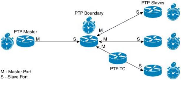
Boundary Clocks and Their Function
A Boundary Clock receives time from the grandmaster through one port and redistributes it through other ports. Instead of forwarding timing packets, it becomes a timing source for downstream devices. This creates smaller timing domains that are more stable because each Boundary Clock acts as a local master.
Boundary Clocks are especially useful in process bus networks where Sampled Values generate heavy traffic. They isolate timing from network load variations and reduce jitter. Each Boundary Clock contains its own timing servo that smooths out fluctuations and maintains a stable output.
Boundary Clock architectures are more scalable and more tolerant of congestion than Transparent Clock designs. They also support redundant timing paths more effectively, making them a common choice in modern digital substations.
The IEC/IEEE 61850-9-3 Power Utility Profile
IEEE 1588 alone is not enough for substation automation. The Power Utility Profile defines exactly how PTP must behave to achieve the accuracy and stability required for IEC 61850-based protection and control.
The profile specifies the timing message rate, the required accuracy of clocks, the permitted jitter, and the performance of both Transparent and Boundary Clocks. It also defines how devices participate in the Best Master Clock Algorithm, which selects the best available grandmaster.
One key requirement of the profile is deterministic behavior. Timing traffic must be predictable, synchronized at defined intervals, and unaffected by network load. The profile restricts message intervals so that all devices follow the same timing rhythm. This is essential for interoperability.
The profile also defines holdover performance, which determines how long a device can maintain accurate time if it temporarily loses its upstream timing reference. High-quality oscillators are required in devices that must tolerate long holdover durations.
Timing Requirements for Sampled Values
In IEC 61850, Sampled Values represent real-time current and voltage measurements. Typical sampling rates include 80 or 256 samples per cycle, depending on the application. For these samples to be meaningful, all merging units must sample at the same instant.
Timing error between merging units can lead to protection miscalculations. Even an error of a few microseconds can cause incorrect estimation of phasors, impedances, or differential currents. For this reason, the Power Utility Profile sets strict limits on maximum time error and jitter.
Timing for Sampled Values must not only be accurate but also stable. If the time difference fluctuates over seconds or minutes, the quality of protection decisions decreases. The timing system must therefore maintain alignment continuously, even under changing traffic conditions.
Best Master Clock Algorithm (BMCA)
The BMCA determines which device becomes the grandmaster. Several devices may be capable of acting as a grandmaster, but only one is active at a time. The BMCA compares priority values, clock quality, time source, and class to select the best one.
If the active grandmaster fails or loses its external reference, the BMCA selects a new grandmaster. This transition must be quick and stable. The Power Utility Profile defines the rules that make this possible. A poorly configured BMCA can cause timing instability, so substation designers must choose clock priority values carefully.
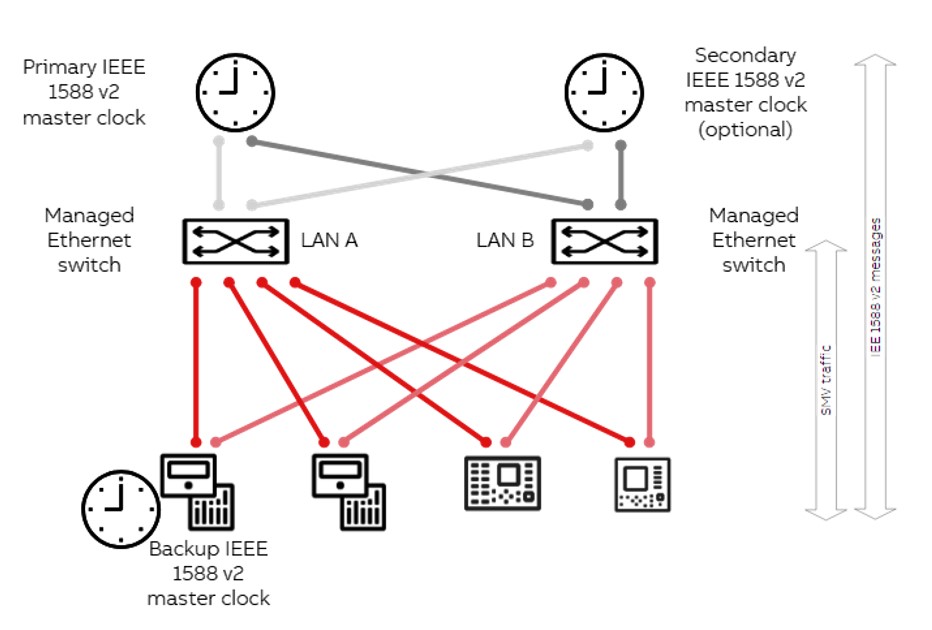
Redundant grandmasters improve reliability. One grandmaster may be connected to one network path, while a backup is connected to another. The BMCA coordinates smooth transitions between them.
Handling Delay, Jitter, and Asymmetry
Even with precise clocks, timing can be distorted if network delays are unpredictable. Delay variation, or jitter, is one of the most important factors affecting timing accuracy. When switches become congested, queue delays change. Transparent Clocks correct for residence time, but Boundary Clocks are often preferred because they isolate timing from traffic variations.
Asymmetry in network paths also affects timing. IEEE 1588 assumes that the forward and reverse path delays are equal. If this is not true—because fibers are different lengths, or because copper and fiber are mixed—the slave clock calculates incorrect time. Designers must minimize or compensate for asymmetry to maintain accuracy.
Fiber paths should be balanced, and long-distance runs should use matched cables. If perfect symmetry is impossible, calibration values can be set in the timing devices so that the known asymmetry is compensated.
Redundancy in PRP and HSR Networks
Digital substations commonly use PRP or HSR for redundancy. Timing traffic must operate correctly under both models. PRP transmits frames on two independent networks, so PTP messages are duplicated. Devices must process these duplicates consistently to avoid timing instability.
HSR sends frames around a ring in two directions. This creates two possible timing paths. Timing devices must ensure that correction values are consistent and that loops do not introduce excessive delay. Boundary Clock architectures are often preferred in HSR networks for this reason.
Redundant timing paths must be symmetrical and must use identical switch configurations to avoid timing inconsistencies during failover. When a network fault occurs, devices may switch paths, and the timing system must continue functioning without noticeable drift.
Designing a Reliable Timing Architecture
A reliable timing system requires careful design. The grandmaster should be placed in a location with stable environment and redundant power. It should have a stable external reference and good holdover capability. Merging units should be placed close to Boundary Clocks to reduce propagation delay. Switches must support precise hardware timestamping and must be configured to prioritize PTP traffic.
Physical paths must be planned to minimize asymmetry. Fiber should be used for long distances. PTP should be placed in a dedicated priority queue and separated from high-bandwidth Sampled Values traffic as much as possible.
PRP networks must maintain identical timing performance on both LANs. HSR networks must ensure consistent correction across both directions of the ring.
Engineers should also consider long-term stability. Temperature changes, equipment aging, and network upgrades can affect timing. Regular testing and monitoring ensure that timing remains within limits.
Troubleshooting Timing Problems
When timing issues appear, they can cause subtle but serious symptoms. Protection devices may show unexplained differential currents, inconsistent event ordering, or unexpected impedance calculations. These symptoms often originate from timing drift.
Troubleshooting begins by checking whether merging units and IEDs remain synchronized. Monitoring PTP messages reveals whether Sync and Follow_Up messages are arriving consistently. Correction fields help identify residence time anomalies in switches. Delay measurements can uncover asymmetry or congestion problems.
If a grandmaster fails or becomes unstable, its clock class changes. Other devices must recognize this change and select a new grandmaster. Logs from Boundary Clocks and merging units help identify whether BMCA transitions occurred smoothly.
In redundant networks, engineers should verify that timing behavior is consistent on both paths. Variation between LAN A and LAN B may indicate misaligned queue settings or inconsistent switch configurations.
Understanding the entire timing chain—from grandmaster to slave clocks—helps isolate issues quickly.
FAQ – IEEE 1588 PTP Time Synchronization in IEC 61850 Digital Substations
What is IEEE 1588 PTP in a digital substation?
IEEE 1588 PTP (Precision Time Protocol) is a timing protocol used to synchronize all devices in an IEC 61850 digital substation. It provides microsecond-level precision required for Sampled Values, protection relays, event recording, and automation functions. The IEC/IEEE 61850-9-3 Power Utility Profile defines how PTP must operate in power systems.
Why is PTP required for Sampled Values (SV) in IEC 61850?
IEC 61850 Sampled Values streams must be aligned in time so protection relays can compare measurements correctly. Even a few-microsecond timing error can cause incorrect phasors, impedance calculations, or differential currents. PTP keeps merging units synchronized within microseconds, ensuring correct SV processing.
What is the IEC/IEEE 61850-9-3 Power Utility Profile?
The IEC/IEEE 61850-9-3 profile defines how IEEE 1588 must behave in power utility automation. It specifies message rates, clock classes, delay requirements, jitter limits, and performance rules for grandmasters, Transparent Clocks, Boundary Clocks, and slave clocks. It ensures interoperability between devices from different manufacturers.
What is the difference between Transparent Clocks and Boundary Clocks?
Transparent Clocks measure the time a PTP packet spends inside a switch and add a correction value. Boundary Clocks terminate PTP and act as a local master for downstream devices. Transparent Clocks correct delay; Boundary Clocks regenerate time. Boundary Clocks are preferred in high-load process bus networks.
How accurate is PTP in an IEC 61850 substation?
With proper switch configuration and compliant clocks, synchronization accuracy can be better than 1 microsecond. Some systems achieve sub-microsecond accuracy. Accuracy depends on clock quality, switch design, network load, queue management, and asymmetry.
Can PTP run on PRP or HSR networks?
Yes. PTP operates on PRP (Parallel Redundancy Protocol) and HSR (High-availability Seamless Redundancy). PTP messages are duplicated on PRP and travel both ways in HSR rings. Timing devices must handle duplicates consistently and ensure that correction values remain stable on both paths.
What happens if the grandmaster clock fails?
If the grandmaster clock fails, devices detect the loss of Announce messages. The Best Master Clock Algorithm (BMCA) selects a new grandmaster automatically. This switchover must be smooth, with minimal time deviation. IEC/IEEE 61850-9-3 defines clock classes and rules that ensure stable transitions.
Conclusion
IEEE 1588 time synchronization, combined with the IEC/IEEE 61850-9-3 Power Utility Profile, forms the backbone of timing in digital substations. Accurate, stable, and predictable time alignment enables reliable Sampled Values, correct protection decisions, precise event logs, and overall system stability.
Transparent Clocks and Boundary Clocks ensure that timing packets flow through the network without unpredictable delay. Redundant architectures ensure continuity under faults. Careful design of network paths, queue priorities, oscillator quality, BMCA settings, and physical topology ensures long-term reliability.
A well-designed timing system transforms digital substations into precise, coordinated, and independently synchronized systems. Time is not just another signal in a digital substation—it is the reference that keeps every device and every protection function aligned.